Civil 3D Beatle

Adventures in Civil 3D and AutoCad Management

Monday, February 25, 2008

The Long and Winding Road

Set up a Sheet Set template in a Nutshell

  1. First Things First
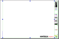
    • Take one of your standard title blocks / borders and put it in a blank drawing on a layout tab. Nothing goes in model space. This drawing will be your sheet set DWT template file.
    • Explode it
    • Save it as a DWT
  2. Custom fields
    • Create custom fields to optimize reuse of data. Without sheet set manager, you would probably just enter MTEXT or attributed blocks all over the place. Some of the text could be repeated 3 or 50 times, depending on how many layouts you have in your final drawing set. One of the best things about sheet set manager is that you can enter all of the project specific data one time and have it flow throughout every sheet in the drawing set.
    • To create a custom field, simply type some MTEXT where ever you want the field to be. Now, highlight the text and right-click and choose “Insert Field”.
    • This will bring up a wizard with all kinds of Field Categories. The only one you really need to care about is the SheetSet category. This will get you up and running quickly so you can tinker with some results. You will want to insert these different fields all over your page in place of the MTEXT.
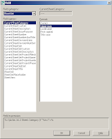
    • You’ll probably notice that Autodesk has not thought of everything, but they leave you room to create your own fields. To create a custom sheet set field, choose the CurrentSheetSetCustom category and then type in a Custom property name at the bottom of the window. Just to give it a whirl, a nice one to try is “City”.
    • I use all UPPERCASE for my custom field names, just so I can tell them apart when I see them all together.
    • Also, document what you call your fields in your CAD Management Wiki because when you utilize the field names later you will find out they are case sensitive.
  3. Add Viewport(s)
    • Create a new viewport and put it in the layout.
    • Add some extra vertices for later.
    • Set your Viewport scale
    • After you have your fields up and running the way you like, you should add duplicates of this layout with different layout scales set up.
    • Save DWT
    • Do a “Save As” and save this dwt as a SSM_Example.dwg
    • Close the SSM_Example.dwg
  4. "Who is your daddy and what does he do?"
    • You are probably wondering when something cool will happen. I think you are thinking that because that is what I was thinking when I was doing this. Be patient – this crop will yield its bountiful fruits shortly. This DWT will feed the example sheet set we are about to set up and it will all begin to make some sense and the light bulb will turn on.
  5. Create the sheet set from scratch
    • Open a new, blank drawing. SSM needs a drawing open to function properly.
    • Open Sheet Set Manager. If you don’t know which button it is, just type SheetSet and the command line and it will appear.
    • Behold SSM (Sheet Set Manager) in all of its’ glorious glory!
    • Hit the dropdown and choose “New Sheet Set”
    • This will open up SSM Wizard.
    • Yes, the SSM Wizard is oddly similar to Mr. Wizard and when you see Mr. Wizard you know something really cool is going to happen!
    • Choose to create the sheet set from Existing Drawings.
    • Give your sheet set file (.dst) a name and a location.
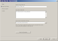
    • Now it begins to come full circle - click the “Sheet Set Properties” button.
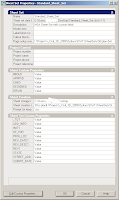
    • Now you will see a bunch of different parameters you can set.
      • Project name, Project number, Sheet creation template, etc.
    • The information displayed on this screen will feed the fields you set up in your DWT.
    • You will notice there is no place to enter data for your custom fields you set up. Click the “Edit Custom Properties” button to add them to the list. Now you can go back and reference your CAD Management Wiki for your list of case-sensitive field names.
    • Each of your custom fields is either a ”Sheet Set” property or a “Sheet” property. Most will likely fall under “Sheet Set” property, but you may have a few that will be unique to each sheet. Add all of your custom fields. When you are done they will all appear on the main properties window for you to fill in the blanks.
    • You know, keep clicking OK and Next...
    • Now, Browse to your SSM_Example.dwg
    • SSM will add the layout with the fields into your sheet set.
  6. Check / Test / Do it all over again from the start / Check / Test again…
    • I know I know, why can't software just work!
    • If it's not working then maybe you have placed some of your custom stuff in the wrong category (Sheet vs Sheet Set properties)
  7. Got It!
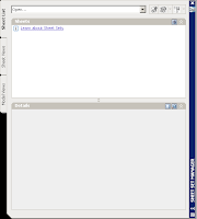
    • If you look over at the SSM window, you should see your new sheet set with a single layout added as a new sheet.
    • Take notice that if you highlight the Sheet Set, all of the properties will be displayed (including your custom properties). The same thing will happen if you high light the single sheet, only now the sheet specific properties are displayed. To edit these properties you can just right-click either one.
  8. Check this sheet out!
    • Double-click the sheet in the sheet set manager to open the sheet. It should open up the sheet / drawing and if you did everything correctly, you should see that your fields are populated with the info you specified in the properties dialog.
    • If it doesn’t look like it worked, do not be discouraged. It took me a few times to work out the kinks in the workflow.
    • Also, like Heidi always says - Save and Regen on every change you make.
  9. Make me a template!
    • Okay, so how do you to set this up so you can “Create from an Example Sheet Set” and not have to add 20 custom fields every time you do this? Simple. Open the sheet set, right click on the layout(s) you have in it and Remove them. Once you are left with the lone Sheet Set file, close it and browse to it with windows explorer and copy it to a wherever it is that you keep your sacred stand files.
    • When somebody wants to create a sheet set with all of those special fields already entered for them, they browse to this .DST file. Now they don’t have to enter all the custom field names every time.
  10. Now what?!?!
    • Once you have got the fields / data flowing together nicely you can go back and make additional layouts at different scales and do some additional neat things. To read more about this, just do a Google search and you will find a number of more intelligent individuals have done more in-depth tutorials on how to get fancy with this tool – I just wanted to give you the short short version. The hardest part of this process is doing it for the first time – once you see the big picture it really isn’t hard to figure out how this could be a big time saver for your peeps.
    • Ok, I won’t make you do the Google search yourself…
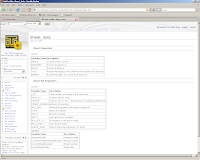
      • Autodesk Whitepaper - http://images.autodesk.com/adsk/files/Organize.pdf
      • Heidi Hewitt Blog- http://heidihewett.blogs.com/my_weblog/2005/10/sheets_happen_a.html
      • Heidi again (from AU 05) - http://www.widom-assoc.com/AU-GD13-5L.pdf3
      • And again with a webcast - https://www120.livemeeting.com/cc/autodesklearning/view?id=ACAD_12_05_07&pw=Audience&cn=

Thursday, February 14, 2008

Beef Jerky

How to Create Customized Complex Linetypes with Embedded Shapes

Step 1 - Open a new DWG and set the drawing / annotation scale to 1 = 1

Step 2 - Insert the block you wish to add to the linetype at 0,0,0 with a uniform scale and explode it

Step 3 - From the Express menu, select Tools and then Make Shape

Step 4 - From the MKSHAPE dialog box, browse to a location where you can save the new Shape file, enter a descriptive name for it select Save

Step 5 - Look to the command line to set several options for your Autocad Shape file. Set the resolution to 200 and select all of the exploded objects that you want in your shape file and press Enter. Civil 3D will show you that the shape was created successfully.

Step 6 - Now, we want to insert the new shape file into the drawing. To insert the shape, type SHAPE at the command line and enter the name of your shape file. You will then be prompted to place it and scale it - we want to put it right on top of the exploded block so we can use the O-snaps.

Step 7 - Next you will want to draw three .25-inch lines to create what will become the dashed line of your linetype. Start at the left-most point on your shape and work your way over. The total length of the line left-to-right should be about 1 inch.

Step 8 - Now, from the Express menu, choose Tools and Make Linetype. The MKLTYPE dialog box will open and prompt you for a name and location for your linetype. If you have an existing linetype file created, you can select it to add this linetype definition to the existing file.

Step 9 - After you choose your lintype file name and location. You will be prompted to Name the linetype within the linetype file and give a description and select the object you want to use to create the linetype. The description can be anything from a verbal description to a simple graphical representation of the linetype itself. When you are prompted to specify the start and end points of the line definition, choose the start and end points of your line or dashed line. When you are prompted to choose the objects, choose your shape and your line or dashed line(s).

Step 10 - Once you hit enter, Autocad will tell you that your linetype is created and loaded. A quick check at your Linetype toobar / drop-down menu will confirm this.

Step 11 - Test your new linetype. Start a new drawing and type Linetype at the command window to load your new linetype. Browse the the saved location of your linetype file to load it.


Wednesday, January 23, 2008

Expert Texpert

A nice fellow I met at AU is getting ready to venture into the world of CAD wiki's as well and wrote me asking for some advice. I ended up writing a nice outline of how I set mine up and thought it may be helpful to others too. This one's for you Vince!

For the user access - everyone has read / write permissions to edit the text and put links in and add photos and stuff. Of course, if somebody creates a wiki page, they have the option of "Locking it down". For instance, here at our company the wiki is used for every department, not just CAD Management. So the head office admin for the engineering department has created her own "Engineering Homepage" with things that are relevant to the Engineering department (city contacts, website links, ect.). She has that main page locked down so nobody can go in and edit it.

Everyone has the option to lock a page down if they created it. As I have been creating my CAD Management wiki pages, I have chosen to not lock any of it down like some of the other departments and have chosen to do so for a few reasons...
1 - because I feel it defeats the purpose of the wiki a little bit
2 - it empowers the users and makes them feel like they own it more
3 - if I create a page and somebody edits it, I get an email saying it was changed and I can easily change it back

I work with only about 50 people who would ever want to change any of the CAD management content, so if it wouldn't be too hard to manage if there was ever a problem with vandalism or something like that.

The first project I did with the wiki was to create an archive of all of the existing CAD standards as they currently were. Simple text, bulleted lists and tables - nothing too fancy. After I was sure I had all of the content in there, I went back and embedded DWF's of some of the drawing examples that were in the old CAD Manual.

After the CAD standards were properly documented, I wanted to create a spot for the users to take over a little bit. There are so many smart users and they will always know the program so much better than me and many of them keep lists of tips and tricks that they use somewhat often. I created a place where they could start creating a directory of all of the tips they had. The trick is to figure out a way to get them to note it in the wiki rather than a piece of paper at their desk (which I still have trouble getting them to do, but that is a people problem - not the wiki).

After I created a nice spot for the users, I wanted to create a virtual library. There are so many white papers, videos and other electronic media out there about cad that is useful - but if it gets printed out its gets thrown away or forgotten or lost. Using Filezilla for my FTP interface, I upload documents / videos / add-ons to the wiki server and then create links to these files in the wiki. I now have a really nice collection of Videos, White papers, student workbooks and cad-related programs organized in a wiki table format that work really well. I even have it organize by discpline, so the surveyors and engineers don't have to look through long lists of stuff that doesn't apply to them.

Nobody except IT and myself have access to the wiki server via FTP to post programs and files. There is an interface in the wiki where users could post files and pictures, but they do not utilize it very much so I am not too worried about it. Again, if you have to deal with a greater number of users, you may want to disable some file posting abilities to increase security.

Other than that, I think you should be fine. I have a section for "Standards", a sections for "Tips and Tricks" and a section for "Digital Media". Inside the standards section, there are a few custom "step by step" instructions I have done with screen shots.

Tuesday, December 11, 2007

Sitting on a corn flake...

We were having a problem with Vault this week and thanks to our reseller we figured it out pretty quickly. One of my users was having some strange issues with x-references through Vault via Civil 3D. He would set up a few X-refs and then check the drawing into the Vault project.
Then he'd go back in to check it out and the host drawing and the x-ref would both be marked as "Not checked into Vault" by Civil 3D. This had me stumped for about 3 hours. I uninstalled Civil 3D and Vault, then reinstalled both - that didn't fix it. I logged in as myself at his workstation and saw that the problem went away, so I figured it must be a corrupt windows profile. I renamed it then logged in as the user and that still didn't fix it.
Finally, I gave up and called my reseller. Apparently the user had accidentally set his working folder to "My Documents" in Vault Explorer. Even though the Toolspace VE was set to the "C:/Civil 3D Projects" directory, I guess the X-ref panorama was set to "My Documents". Once the Vault Explorer working folder was set to match the Civil 3D Toolspace, all the problems went away.

Tuesday, December 4, 2007

Everbody's Got Something To Hide Except For Me And My Wiki

So, I haven't been able to make a good post about the CAD Management wiki because...I was updating the wiki based on user feedback. That is one of the best things about the wiki system - it is so flexible and easy to change. Rather than ramble on and on about what I think is so great about the wiki, I'll just give you a bulleted list of features that I think can save your firm a small fortune.

  1. Easy back-end coding format that makes it possible for anyone to add content - not just the IT-inclined.
  2. Ability to easily post audio, video, DWF, white papers and any other electronic media you can think of
  3. Revision control for anything posted - if somebody edits something you've posted and you don't like it you can simply hit the "undo" button and go back to that previous version of the page.
  4. You can lock down content you don't want to editable. For instance, the CAD standards.
  5. You can create quizzes right inside your wiki page. You can test your staff on CAD standards easily every year and even set minimum scoring standards for the test.
  6. Users have to log in to edit anything, so if there are certain people who you know don't have to edit anything, they can still view it but not ever have editing capabilities.
There are way too many features for me to list and talk about on here, but I have put some screen shots down below here, so you can see the simplicity and the power of the software. There are a lot of different wiki software packages out there and you should choose the one that best meets your firms needs - we use Tiki-Wiki. If you have a smart IT supporting you, the possibilities are numerous. Currently, our email, project management package, wiki intranet and instant messaging system are all open source, free and fully integrated with each other. I'll post about that another time. Check out the pictures and let me know what you think!


Wednesday, November 7, 2007

12 O'Clock a meeting, 'round the table...

How would you communicate to your management team about moving forward with Civil 3D? Would you tell them to abandon some of their old habits in order to make it a success? I think you would have to unless you were setting yourself up for failure. Here are some things I think it is necessary to tell your projects managers and department heads before moving forward with a full implementation of Civil 3D...

  • Give Them A Deadline - In order to create effective CAD management and design standards, your company should move away from the older CAD programs and conform to a single version of CAD. You can begin to realize this by ensuring that all new projects started after an approved deadline are created with the Civil 3D software and stored on the Vault server.
  • Talk About CAD Standards - As your company continues forward using Civil 3D 2008 and Vault, new standards and best practices will be developed and they should be recorded in a new Civil 3D CAD Standards Manual. This will provide a centralized, easy-to-access location for your company to build a new knowledge base for Civil 3D.
  • Mention The Learning Curve - Civil 3D 2008 is different from all of the previous CAD programs. It will require that each team think differently about existing processes and develop new workflows to fully take advantage of the 3-D civil engineering model. There is potential for a significant learning curve for some users and they may have to “re-learn” how to do some tasks / parts of their job.
  • Have the PMs Adjust Their Deadlines (If Possible) - Project Managers should try to adjust their submittal and milestone deadlines on all new projects with some buffer time to compensate for the learning curve associated with Civil 3D and Vault. Team members will encounter issues they have never had to deal with before and if they feel are too pressured to meet deadlines they may revert back the old software instead of learning new skills in Civil 3D.
  • Get Some Power Users - Your company should have two to three “power users” per team - depending on the size and scope of the team and projects they deal with. These are users who have attended training and / or worked with Civil 3D and will be able to help individuals / teams troubleshoot issues with Civil 3D and Vault. Although your company will be learning a lot in the first few months, teams will get caught up and the rhythm of production should return to normal quickly.
  • PMs Should Monitor Their Teams - Traditionally, Project Managers have not concerned themselves with what version of software was used to create the CAD drawings. They just want to see the final product. This must should change for the first four to six months while the new software is being implemented. Project Managers need to actively monitor and be aware of what CAD software is being used on each new project. They should report any issues / problems that need in-house assistance or outside consultation to the CAD Manager so they can be resolved as quickly as possible.
  • Hold Weekly Meetings - Project Managers should hold weekly meetings with their team to discuss Civil 3D / Vault “Lessons Learned” and best practices. This will facilitate better communication between team members regarding new skills sets, processes and problems areas they have encountered while using Civil 3D. This will also give the Project Managers the opportunity to monitor the pace at which their team is learning the new software. If team meetings are used to address other issues, it may be appropriate to appoint a Senior CAD Technician to report to their respective project manager each week with a progress report.

Thursday, October 11, 2007

I read the news today, oh boy...

There was an article posted up on how Virginia Tech is implementing Civil 3D into some of their courses and even devoting some higher-level labs to Civil 3D completely. I never went to Virginia Tech, but there are lots of BOD members that went to VA Tech. As soon as I saw the article I made sure to email it out to the whole company and print it out and leave it on some important desks. Anything to show management that their school is on board with moving towards the new frontier. Here is a link to the article... http://images.autodesk.com/adsk/files/va_tech_final.pdf